SAMSUNG PPM63H3X/XSF
PLASMA DISPLAY

SERVICE MODE AND POWER SUPPLY CIRCUIT
SERVICE MODE
HOW TO ENTER TO SERVICE MODE
1. Turn the power off and set to stand-by mode.
1. Turn the power off and set to stand-by mode.
2. Press the buttons of the transmitter in this order; Info-Menu-Mute-Power or
Mute-1-8-Power to turn the set on.
3. The set turns on and enters service mode.
UP/DOWN Key > Cursor move to select items
LEFT/RIGHT Key > Enable to increase and
decrease the data of the selected items
White Balance Adjustment
1. W/B Adjustment is required for the following
four modes: DVI > DTV > PC > CVBS(VIDEO) > CVBS(VIDEO PIP)
2. Adjustment Method (DVI, DTV, PC : VG828, CVBS
: Adjust RF signals to match the Toshiba pattern (in-house signal)
A. Adjust the target set by adjusting the panel
logic and the video DNIe adjustment register in register in order to determine
the referential W/B of the panel with a DVI input, which is the full digital
path.
B. For DTV adjustment, adjust the adjustment
register of ad9888 to align the DTV signal to the DNIe and logic panel value
which was fixed with a DVI adjustment so that they are in effect considered to
be the same signals. (At this time, do not adjust the gain of AD988> the
Highlight W/B does not need to be adjusted since its deviation falls within
valid distribution range.)
C. PC adjustment is same as DTV adjustment. (The
offset can be applied to the values obtained through DTV adjustment. However,
additional adjustment is required for Y, Cb, and Cr of DTV since PC processes
R, G, and B signals.)
D. cvbs adjustment is performed with the Toshiba
pattern (in-house signal) and differs from the VG828 signals in the above three
modes. Hence, it should be performed with the same method of DVI adjustment.
E. Finally, activate PIP in video mode, and
repeat W/B adjustment.
Thus, Micom saves the W/B data separately for
each memory mode of the block
DETAILED POWER SUPPLY CIRCUIT


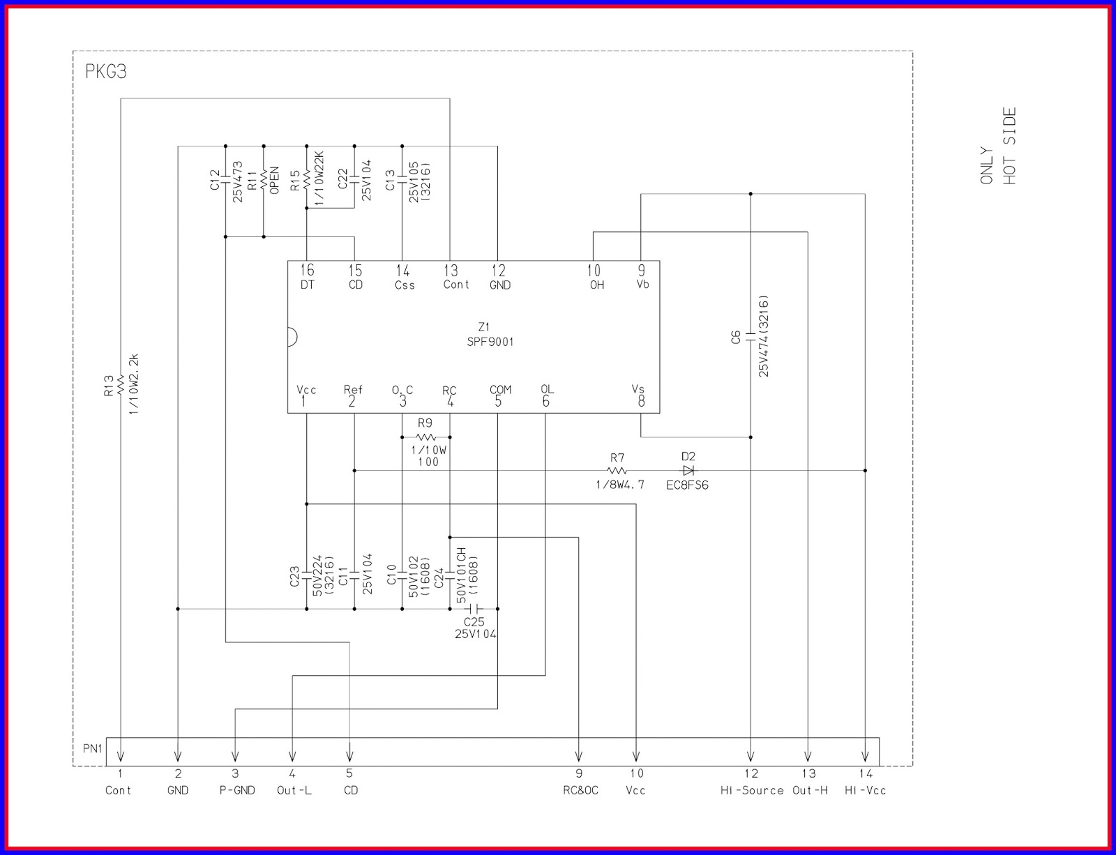


CLICK ON THE IMAGES TO ZOOM IN