TOSHIBA REGZA 32AV555D

SERVICE MODE AND MOTHER BOARD POWER REGULATOR CIRCUIT
Service Mode
Entering to Service Mode
Entering to Service Mode
1. Set VOLUME to minimum and press MUTE button once on remote control.
2. Press MUTE button again and hold button down.
3. While holding the MUTE button, press MENU button
on TV set.
Key Function in the Service Mode
The following key entry during display of adjustment menu provides special functions.
The following key entry during display of adjustment menu provides special functions.
Test signal selection > INPUT button (on
remote control)
Selection of the adjustment items > CH UP/DOWN
(on TV) or MENU UP/DOWN (on remote control)
Change of the data value > Volume +/- (on TV)
or MENU RIGHT/LEFT (on remote control)
Adjustment menu mode ON/OFF > MENU button (on
TV)
Initialization of the memory (IC152) > CALL +
CH UP button on TV
Automatic A/D Adjustment (Component, Composite
(PAL, NTSC), RGB) > 7 button
Self diagnostic display ON/OFF > 9 button
Selecting the Adjusting Item
Every pressing of MENU UP button in the service mode changes the adjustment items in the order of table below. (MENU DOWN button for reverse order)
Every pressing of MENU UP button in the service mode changes the adjustment items in the order of table below. (MENU DOWN button for reverse order)
Setting Panel Option Data
Panel option data is subject to OPT4 and OPT5.
Enter to service mode and select menu of OPT4 or OPT5 by pressing P UPor P DOWN during display of adjustment menu. After selecting OPT4 or OPT5, press + or - to set OPT4 or OPT5 value
Panel option data is subject to OPT4 and OPT5.
Enter to service mode and select menu of OPT4 or OPT5 by pressing P UPor P DOWN during display of adjustment menu. After selecting OPT4 or OPT5, press + or - to set OPT4 or OPT5 value
32AV555D/554D > SHARP > OPT 4 = 0x02 ,OPT
5 = 0x05
37AV555D/554D > LGD OPT 4 = 0x01, OPT 5 = 0x06
42AV555D/554D > LGD > OPT 4 = 0x01, OPT 5
= 0x07
Exit from Service Mode
Pressing POWER button to turn off the TV once.
Pressing POWER button to turn off the TV once.
Test Signal Selection
Every pressing of INPUT button on the remote control changes the built-in test patterns on screen.
Every pressing of INPUT button on the remote control changes the built-in test patterns on screen.
Self Diagnostic Function
1. Press "9" button on remote control during display of adjustment menu in the service mode. The diagnosis will begin to check if interface among IC's is executed properly.
2. During diagnosis, the following displays are shown.
# Self check display and Item are subject to the models.
1. Press "9" button on remote control during display of adjustment menu in the service mode. The diagnosis will begin to check if interface among IC's is executed properly.
2. During diagnosis, the following displays are shown.
# Self check display and Item are subject to the models.
(1) Firmware :
Version information of microprocessor
Series name (AAAA) and market area (BB) and software program version (000_000).
(2) Time : Total hour of turn the TV on. (Unit : H)
(3) BL_STATUS :
Counter for saving BackLight on error1.
This value is counted till 99 (Decimal).
(4) Bus line : -- "OK" is normal
SCL-GND (Red indication) : SCL-GND short circuit
SDA-GND (Red indication) : SDA-GND short circuit
SCL-SDA (Red indication) : SCL-SDA short circuit
(5) Bus cont : --- "OK" is normal.
NG is abnormal (Red indication).
(6) Block
UV : TV reception mode
V1 - V6 : VIDEO 1-6 input mode
DTV : DTV mode
NG is abnormal (Red indication).
(6) Block
UV : TV reception mode
V1 - V6 : VIDEO 1-6 input mode
DTV : DTV mode
Version Check Mode
1. Press "9" button twice on remote control during display of adjustment menu in the
service mode.
The version of main MPU will be checked.
2. During Version Check, the following displays are shown.
# Version check display and Item are subject to the models.
1. Press "9" button twice on remote control during display of adjustment menu in the
service mode.
The version of main MPU will be checked.
2. During Version Check, the following displays are shown.
# Version check display and Item are subject to the models.
1) MAIN MPU :
Version information of microprocessor
Series name and Code Program Version (5 figure number) and software program
version (000_000).
(2) EEPROM :
Version information of EEPROM : Display 1 byte data.
(3) OPTION :
Option information : Display eight numbers of 1 byte data.
(4) HDMI EDID :
EDID data check item.
OK : EDID data is enable.
NG : EDID data is disable.
(5) BL Ver
Version information of Boot Loader software as Toshiba release.
(6) AP Ver
Version information of Application software as Toshiba release.
(7) A/D Adjust
A/D adjustment item.
COMP : Component input
RGB : RGB Signal (SCART input)
NTSC : NTSC (60 Hz) SD signal (composite input).
PAL : PAL (50 Hz) SD signal (composite input).
OK : A/D adjustment set correctly.
NG : A/D adjustment set incorrect.
(8) Memory Data Version
Version information of EEPROM.
DRMA**** means model number of EEPROM.
REV** means version of EEPROM.
(9) Model Name
Model name information (ascii code). : Display 8 byte data.
(10) LCD Panel Vendor information display
The following Panel Vendor (DDD) and screen size (00) and displayed.
Example : AUO-32 (1080p) indicates that Vendor is AUO and Screen Size is 32 inch
and Full HD panel
Status Check Mode
1. Press "9" button thrice on remote control during display of adjustment menu in the
service mode.
The status of this model will be checked.
2. During Status Check, the following displays are shown.
* Status check display and Item are subject to the models.
1. Press "9" button thrice on remote control during display of adjustment menu in the
service mode.
The status of this model will be checked.
2. During Status Check, the following displays are shown.
* Status check display and Item are subject to the models.
(1) MAIN :
Main source information :
Display RF position number (0 - 999) on the main screen, or Input Source
(EXT1/2/3/HDMI etc.)
(2) MAIN FORMAT :
Display Video format information
(3) MAIN PLL :
Main PLL information : Display 1 byte data at eight.
Main source information :
Display RF position number (0 - 999) on the main screen, or Input Source
(EXT1/2/3/HDMI etc.)
(2) MAIN FORMAT :
Display Video format information
(3) MAIN PLL :
Main PLL information : Display 1 byte data at eight.
Setting Hotel Mode
Enter to service mode and select Hotel Mode menu by pressing MENU UP or DOWN . After selecting Hotel Mode, press MENU RIGHT or LEFT to enter details setting in Hotel Mode.
To select menu, press MENU RIGHT or LEFT and press OK to enter the adjustment menu of the following table data.
To move the cursor in the adjustment, press MENU RIGHT or LEFT.
Software Upgrade
1. Unplug AC Power.
2. Insert USB Flash memory containing software to TV set.
3. Plug AC Power.
4. Progress bar is shown on TV screen while upgrading. "100 %" is shown when completed.
Never power off while upgrading.
5. Unplug AC Power.
6. Remove USB Flash memory.
7. Plug AC Power
1. Unplug AC Power.
2. Insert USB Flash memory containing software to TV set.
3. Plug AC Power.
4. Progress bar is shown on TV screen while upgrading. "100 %" is shown when completed.
Never power off while upgrading.
5. Unplug AC Power.
6. Remove USB Flash memory.
7. Plug AC Power
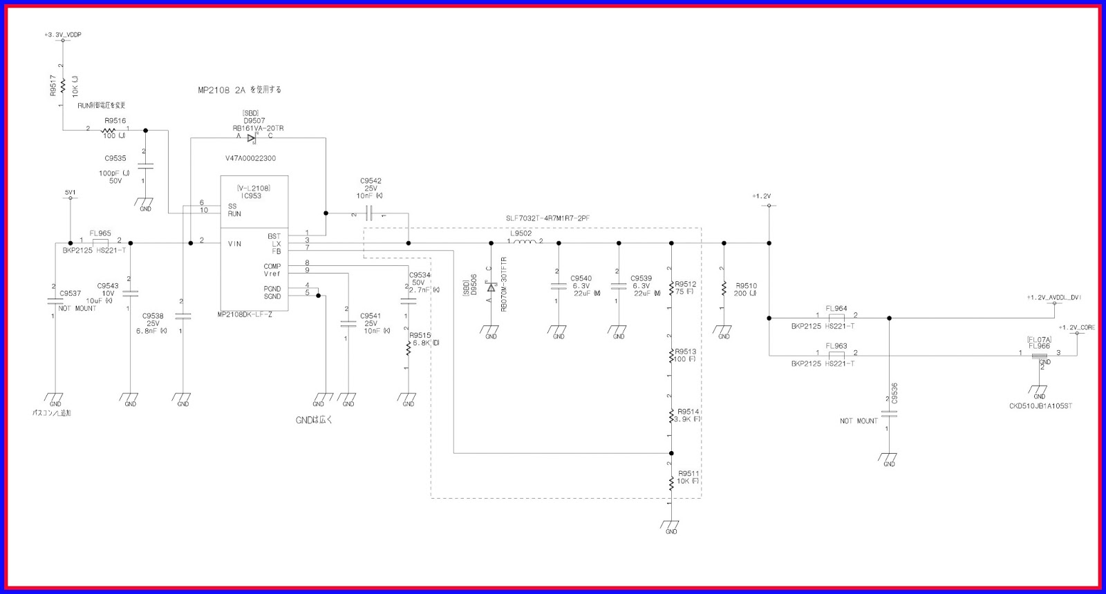
MOTHER BOARD POWER REGULATOR CIRCUIT
1.2V REGULATOR
2.6 V REGULATOR

3.3 V REGULATOR

CLICK ON THE IMAGES TO ZOOM IN