SUBWOOFER
JBL YST-SW012
DISASSEMBLING AND CIRCUIT DIAGRAM
DISASSEMBLY PROCEDURES
(Remove parts in the order as numbered.)
Disconnect the power cable from the AC outlet.
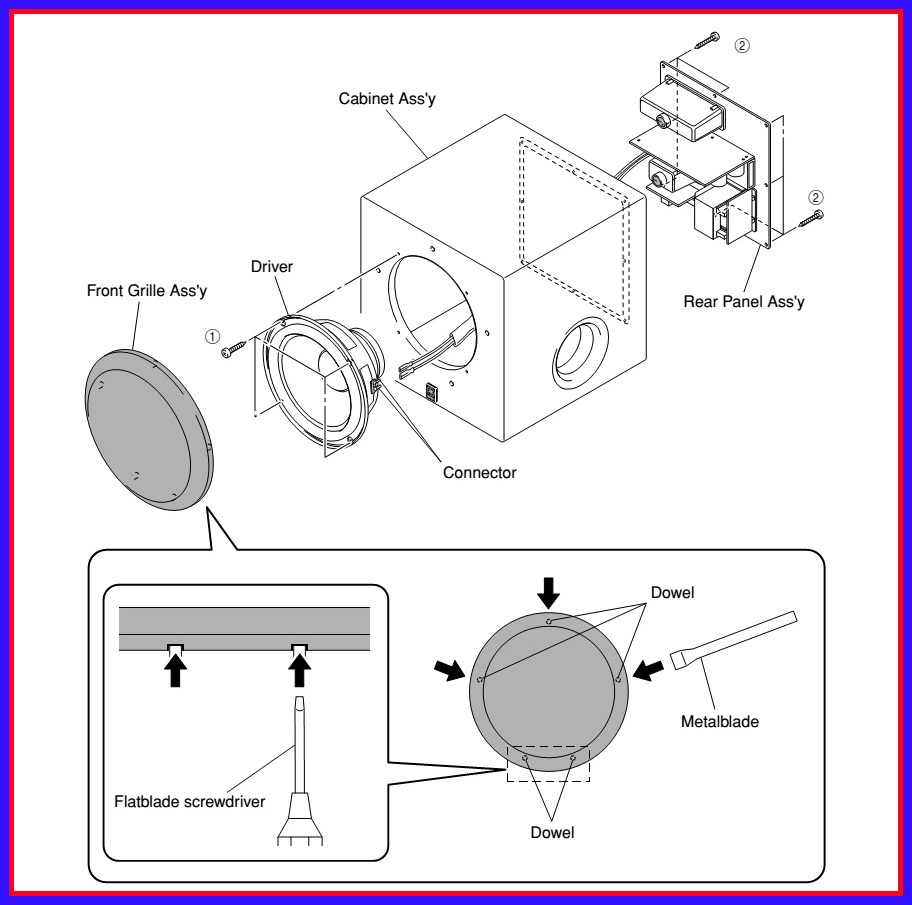
1. Removal of Front Grille
#The Front Grille is fixed to the cabinet with dowels at 5 locations.
As a flatblade screwdriver is used for removal, use special care not to cause damage to the Cabinet.
a. Using the flatblade screwdriver inserted in the gap between the Front Grille and the Cabinet (bottom side first), push up the Front Grille.
b. Remove the Front Grille Ass’y by lifting a metalblade up.
# When installing the Front Grille , apply quick-drying bond or the like to dowels and then fit them into dowel holes for secure installation. (The Front Grille will come off easily if its dowels are fitted into dowel holes without applying quickdrying bond or the like.)
(Remove parts in the order as numbered.)
Disconnect the power cable from the AC outlet.
1. Removal of Front Grille
#The Front Grille is fixed to the cabinet with dowels at 5 locations.
As a flatblade screwdriver is used for removal, use special care not to cause damage to the Cabinet.
a. Using the flatblade screwdriver inserted in the gap between the Front Grille and the Cabinet (bottom side first), push up the Front Grille.
b. Remove the Front Grille Ass’y by lifting a metalblade up.
# When installing the Front Grille , apply quick-drying bond or the like to dowels and then fit them into dowel holes for secure installation. (The Front Grille will come off easily if its dowels are fitted into dowel holes without applying quickdrying bond or the like.)
2. Removal of Driver
a. Remove 4 screws (1) and remove the Driver.
b. Disconnect the connector connected to the terminal of the Driver.
3. Removal of Rear Panel
a. Remove 8 screws (2) and remove the Rear Panel.
* Screws (2) are identified with arrow marks ( <= ).
b. Disconnect the connector connected to the terminal of the Driver.
3. Removal of Rear Panel
a. Remove 8 screws (2) and remove the Rear Panel.
* Screws (2) are identified with arrow marks ( <= ).
When Checking the P.C.B..
# Connect all the connectors removed during disassembly back to the original positions.
# Spread the Rubber Sheet and Cloth for insulation purpose and place the Rear Panel on the Rubber Sheet and Cloth.
# Connect all the connectors removed during disassembly back to the original positions.
# Spread the Rubber Sheet and Cloth for insulation purpose and place the Rear Panel on the Rubber Sheet and Cloth.

CIRCUIT DIGRAM

CLICK ON THE IMAGE TO ZOOM IN