Contents of this article
- Disassembling the BDP
- Firmware update BY CD and USB
Category: Bluray player repair
SHARP BD-HP35S
UPGRADING THE VERSION
1. Procedure with a CD
1. Write the updated software on a CD to prepare the version-upgrading CD.
2. Connect the set to the monitor with an HDMI cable. (Keep the HDMI cable connected until the version-upgrading has been completed.)
3. Using the “POWER” key (on the set itself or on the remote controller), turn on the power.
* Do not turn on the power with the “EJECT” key.
4. Press the “EJECT” key to open the tray. Place the upgrading CD on the tray and press the “EJECT” key again to close the tray.
5. The CD is opened and the power turns off itself.
6. The power turns on itself and the upgrading gets started.
LCD display: V-UP blinking > V-UP kept on
Mode display: Blue LED blinking > Blue LED kept on
Monitor screen: Upgrading progress displayed
7. When the software has been 100% overwritten, the tray opens itself and the power turns off itself.
8. Take the CD out of the tray and press the “POWER” key to turn on the power again.
9. When the wallpaper shows up, hold down the “POWER” key to do the resetting. (Keep the “POWER” key depressed until the RESET message appears on the LCD. (About 10 seconds))
10.Press the “POWER” key again to turn on the power.
11.When the wallpaper shows up again, move from [Settings] to [Version] to make sure the software is upgraded.
12.When the upgrading has been successfully made, close the [Version] confirm screen and turn off the power. If it has failed, take the procedure over again from Step 3 above.
2. Procedure with a USB memory
1. Write the updated software on a USB memory to prepare the version-upgrading USB memory.
2. Connect the set to the monitor with an HDMI cable. (Keep the HDMI cable connected until the version-upgrading has been completed.)
3. Using the “POWER” key (on the set itself or on the remote controller), turn on the power.
* Do not turn on the power with the “EJECT” key.
4. Insert the upgrading USB memory into the USB port.
5. When the USB memory has been recognized (the “x” mark on the USB icon disappears and the USB recognition on-screen display appears),
move from [Settings], [Software Update Settings], [Manual Update] to [USB Memory], and then press the “ENTER” or “ > ” key.
6. Press “OK” on the USB recognition confirm screen.
7. The power turns on itself and the upgrading gets started.
LCD display: V-UP blinking > V-UP kept on
Mode display: Blue LED blinking > Blue LED kept on
Monitor screen: Upgrading progress displayed
8. When the software has been 100% overwritten, the power turns off itself.
9. Draw the USB memory out of the USB port and press the “POWER” key to turn on the power again.
10.When the wallpaper shows up, hold down the “POWER” key to do the resetting. (Keep the “POWER” key depressed until the RESET message appears on the LCD. (About 10 seconds))
11.Press the “POWER” key again to turn on the power.
12.When the wallpaper shows up again, move from [Settings] to [Version] to make sure the software is upgraded.
13.When the upgrading has been successfully made, close the [Version] confirm screen and turn off the power. If it has failed, take the procedure over again from Step 3 above.
DISASSEMBLING
Removing the Top Cabinet and
Front Panel Ass’y
1. Remove the 3 lock screws 1 , 2 lock screws 2 and detach the Top Cabinet.
2. Unhook claws of the Front Panel and detach the Front Panel Ass’y.
1. Remove the 3 lock screws 1 , 2 lock screws 2 and detach the Top Cabinet.
2. Unhook claws of the Front Panel and detach the Front Panel Ass’y.

Removing the Rear Panel
1. Remove the 2 lock screws 3 , 1 lock screw 4 , 2 lock screws 5 and detach the Rear Panel.
1. Remove the 2 lock screws 3 , 1 lock screw 4 , 2 lock screws 5 and detach the Rear Panel.

Service ManualRemoving the BD DRIVE Unit
1. Disconnect the 2 FFC Connectors.
2. Remove the 4 lock screws 6 and detach the BD DRIVE Unit.
3. Detach the Tray Blind Cover.
1. Disconnect the 2 FFC Connectors.
2. Remove the 4 lock screws 6 and detach the BD DRIVE Unit.
3. Detach the Tray Blind Cover.

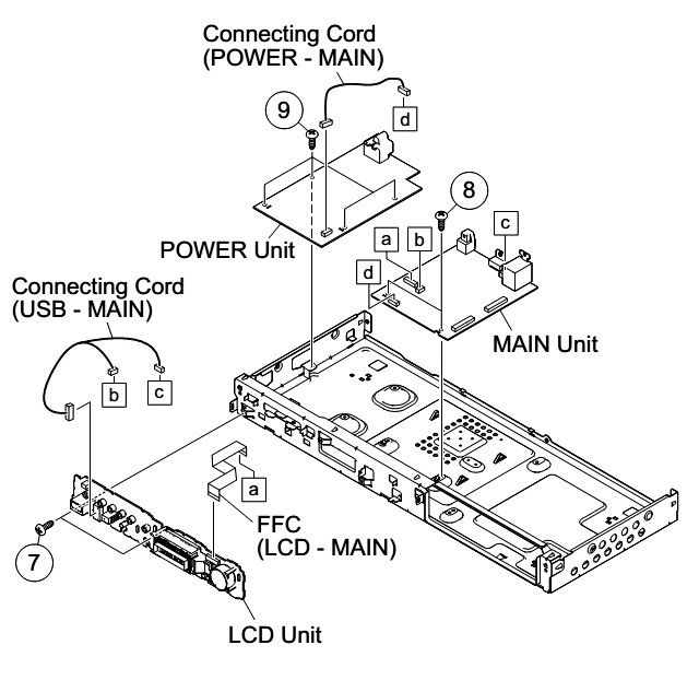
Removing the LCD Unit, MAIN Unit
and POWER Unit
1. Disconnect the FFC (LCD - MAIN).
2. Disconnect the Connecting Cord (USB - MAIN).
3. Remove the 2 lock screws 7 and detach the LCD Unit.
4. Disconnect the Connecting Cord (POWER - MAIN).
5. Remove the 2 lock screws 8 and detach the MAIN Unit.
6. Remove the 4 lock screws 9 and detach the POWER Unit.