Category: Laptop Repair and Service
Contents of this article
- How to check the AC adapter
- How to check the battery pack
- Dismantling the key board
Acer Ferrari 1100
System Check Procedures
External Diskette Drive Check
Do the following to isolate the problem to a controller, driver, or diskette. A write-enabled, diagnostic diskette is required.
NOTE: Make sure that the diskette does not have more than one label attached to it. Multiple labels can cause damage to the drive or cause the drive to fail.
Do the following to select the test device.
1. Boot from the diagnostics diskette and start the diagnostics program.
2. See if FDD Test is passed as the program runs to FDD Test.
3. Follow the instructions in the message window.
If an error occurs with the internal diskette drive, reconnect the diskette connector on the system board. If the error still remains:
1. Reconnect the external diskette drive/DVD-ROM module.
2. Replace the external diskette drive/CD-ROM module.
3. Replace the main board.
External CD-ROM Drive Check
Do the following to isolate the problem to a controller, drive, or CD-ROM. Make sure that the CD-ROM does not have any label attached to it. The label can cause damage to the drive or can cause the drive to fail.
Do the following to select the test device:
1. Boot from the diagnostics diskette and start the diagnostics program.
2. See if CD-ROM Test is passed when the program runs to CD-ROM Test.
3. Follow the instructions in the message window.
If an error occurs, reconnect the connector on the System board. If the error still remains:
1. Reconnect the external diskette drive/CD-ROM module.
2. Replace the external diskette drive/CD-ROM module.
3. Replace the main board.
Keyboard or Auxiliary Input Device Check
Remove the external keyboard if the internal keyboard is to be tested. If the internal keyboard does not work or an unexpected character appears, make sure that the flexible cable extending from the keyboard is correctly seated in the connector on the system board.
If the keyboard cable connection is correct, run the Keyboard Test. If the tests detect a keyboard problem, do the following one at a time to correct the problem. Do not replace a non-defective FRU:
1. Reconnect the keyboard cables.
2. Replace the keyboard.
3. Replace the main board.
The following auxiliary input devices are supported by this computer:
# Numeric keypad
External keyboard
If any of these devices do not work, reconnect the cable connector and repeat the failing operation.
Memory check
Memory errors might stop system operations, show error messages on the screen, or hang the system.
1. Boot from the diagnostics diskette and start the doagmpstotics program (please refer to main board.
2. Go to the diagnostic memory in the test items.
3. Press F2 in the test items.
4. Follow the instructions in the message window.
NOTE: Make sure that the DIMM is fully installed into the connector. A loose connection can cause an error.
Power System Check
To verify the symptom of the problem, power on the computer using each of the following power sources:
1. Remove the battery pack.
2. Connect the power adapter and check that power is supplied.
3. Disconnect the power adapter and install the charged battery pack; then check that power is supplied by the battery pack.
If you suspect a power problem, see the appropriate power supply check in the following list:
Check the Power Adapter
Check the Battery Pack
Check the Power Adapter
Unplug the power adapter cable from the computer and measure the output voltage at the plug of the power adapter cable. See the following figure
Unplug the power adapter cable from the computer and measure the output voltage at the plug of the power adapter cable. See the following figure

1. If the voltage is not correct, replace the power adapter.
2. If the voltage is within the range, do the following:
Replace the System board.
If the problem is not corrected, see “Undetermined Problems” on page 124.
If the voltage is not correct, go to the next step.
NOTE: An audible noise from the power adapter does not always indicate a defect.
3. If the power-on indicator does not light up, check the power cord of the power adapter for correct continuity and installation
Check the Battery Pack
To check the battery pack, do the following:
From Software:
1. Check out the Power Management in control Panel
2. In Power Meter, confirm that if the parameters shown in the screen for Current Power Source and Total
Battery Power Remaining are correct.
3. Repeat the steps 1 and 2, for both battery and adapter.
4. This helps you identify first the problem is on recharging or discharging.
From Hardware:
1. Power off the computer.
2. Remove the battery pack and measure the voltage between battery terminals 1(+) and 6(ground).
3. If the voltage is still less than 7.5 Vdc after recharging, replace the battery.
To check the battery charge operation, use a discharged battery pack or a battery pack that has less than 50% of the total power remaining when installed in the computer.
If the battery status indicator does not light up, remove the battery pack and let it return to room temperature.
Re-install the battery pack.
If the charge indicator still does not light up, replace the battery pack. If the charge indicator still does not light up, replace the DC/DC charger board.
Touchpad Check
If the touchpad doesn’t work, do the following actions one at a time to correct the problem. Do not replace a non-defective FRU:
1. Reconnect the touchpad cables.
2. Replace the touchpad.
3. Replace the system board.
After you use the touchpad, the pointer drifts on the screen for a short time. This self-acting pointer movement can occur when a slight, steady pressure is applied to the touchpad pointer. This symptom is not a hardware problem. No service actions are necessary if the pointer movement stops in a short period of time.
Removing the Keyboard
1. Remove the Battery Pack
2. Push down on the lock and release the latches securing the keyboard to the upper case.
1. Remove the Battery Pack
2. Push down on the lock and release the latches securing the keyboard to the upper case.

3. Carefully pry loose the keyboard and turn it over on the touchpad
area.

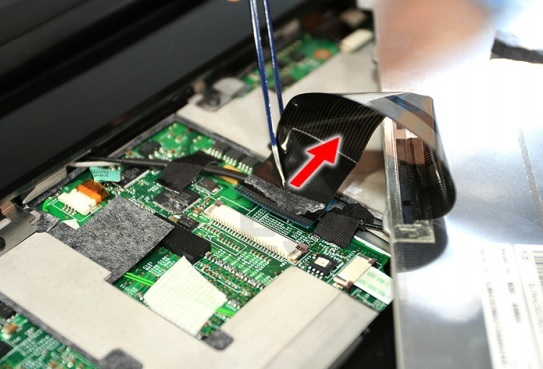
4. Remove the adhesive strip over the connector.
5. Disconnect the keyboard cable from the main board to remove the
keyboard.