Category: Smart Phone Repair and service
Contents of this article
- How to remove the case
- How to remove the battery
- How to remove earpiece and speaker
HTC One M8
DISASSEMBLING PROCEDURE
Removing Rear Cover
There are two front grills on either side of the smartphone’s
display. The grills are secured in place with a small amount of adhesive. Use a
heat gun or blow dryer to soften the adhesive. This will make it easier to
remove the grills from the M8.
 There are two front grills on either side of the smartphone’s display. The
grills are secured in place with a small amount of adhesive. Use a heat gun or
blow dryer to soften the adhesive. This will make it easier to remove the
grills from the M8.Now, locate and remove the two small Phillips screws (#00)
that secure the display assembly to the body of the smartphone (marked with
orange circles). Next, locate and remove the four torx screws (T5) on the
other side of the M8 that also secure the display assembly to the body/housing
of the smartphone (marked with orange circles).
There are two front grills on either side of the smartphone’s display. The
grills are secured in place with a small amount of adhesive. Use a heat gun or
blow dryer to soften the adhesive. This will make it easier to remove the
grills from the M8.Now, locate and remove the two small Phillips screws (#00)
that secure the display assembly to the body of the smartphone (marked with
orange circles). Next, locate and remove the four torx screws (T5) on the
other side of the M8 that also secure the display assembly to the body/housing
of the smartphone (marked with orange circles).


Insert the precision knife between the rear cover and the
M8’s display assembly to free the first of many clips that secure the LCD and
touch screen assembly in place.
Once there is separation between the rear cover and display assembly, use the
triangle plastic opening tool to work around the perimeter of the smartphone
until the rear cover is completely removed.

Removing Motherboard
First, locate and remove the two small Phillips screws (#00)
that secure the connection for the battery terminal (marked with solid orange
circles).
Next, locate and remove the two coaxial cable connec tions that are also secured to the motherboard (marked with open orange circles). There are two pieces of protective tape over the top of the motherboard. Use the heat gun to help soften and peel up the tape.
Next, locate and remove the two coaxial cable connec tions that are also secured to the motherboard (marked with open orange circles). There are two pieces of protective tape over the top of the motherboard. Use the heat gun to help soften and peel up the tape.

Now, locate and remove the three T5 torx screws that secure
the motherboard down to the center of the M8. (marked with solid orange
circles).
Next, locate and remove the three coaxial cable connections. There are two near
the rear-facing camera and the one by the loudspeaker (marked with open orange
circles).
Six locking sockets secure the motherboard’s ribbon cables in place. Release their locks by flipping the opposite side of the ribbon cable up 90 degrees, and then gently slide the cables out their sockets (marked with orange rectangles).
Six locking sockets secure the motherboard’s ribbon cables in place. Release their locks by flipping the opposite side of the ribbon cable up 90 degrees, and then gently slide the cables out their sockets (marked with orange rectangles).
You can now lift the motherboard up and out.Be careful
when maneuvering it through the cables and tape so that no damage occurs.

Next, remove the remainder of tape that is protecting the
ribbon cables on the smartphone. Use heat, if necessary, to make it easier to
remove the tape. Do not forget about the volume rocker portion of the ribbon cable,
and be careful not to damage it when removing the remaining tape (marked with
orange arrow).

Use additional heat to soften the securing adhesive holding
the volume button in place and then with the curved tweezers remove the volume
button from the HTC One (M8).
First, locate and follow the wire coming off the back of the vibrator. Pull its
small plug from the locking socket. Next, use the fine tip curved tweezers to
remove the vibrator from its housing and lift it out.

The wafer connection for the front-facing camera is slightly
covered by a plastic cover. Remove the cover and use the fine tip curved
tweezers to release the wafer connector (marked with orange arrow).
Now, locate and remove the four small Phillips screws (#00)
that secure the daughterboard to the back of the display assembly. Next,
release the ribbon cables in the two locking sockets that are located on either
side of the daughter board (marked with orange rectangles).

You can now carefully remove the board from the M8. There
are two wafer connections on the bottom of the board that might need additional
maneuvering to completely remove the board.
Removing Front-Facing Camera
Use the fine tip curved tweezers to lift the front facing
camera from its housing and remove it.

Removing Rear-Facing Camera
Locate and remove the single small Phillips screw (#00)
that secures the rear-facing camera in place (marked with an orange circle). Now
use the fine tip curved tweezers to lift the rear-facing camera from its
housing and remove it .

Removing Earpiece and Loudspeaker
The earpiece speaker is held in place with adhesive. Use
a small amount of heat to soften the adhesive, if necessary. Then use the fine
tip curved tweezers to lift the earpiece speaker from its housing and remove
it. The loudspeaker is also held in place with adhesive. Use a small amount of heat
to soften the adhesive, if necessary. Then use the fine tip curved tweezers to
lift the loudspeaker up,

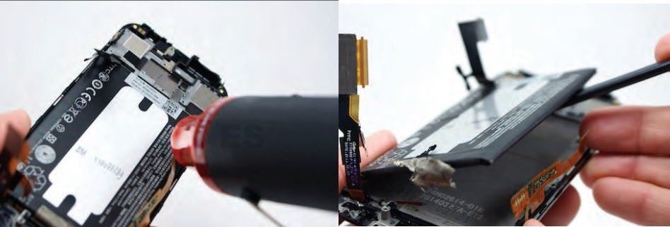
Removing Battery
The battery is held in place with two strips of
heavy-duty adhesive. To avoid damage to the battery, use the heat gun or blow
dryer to soften the adhesive before trying to remove the battery.
Use the nylon spudger to gently pry the battery up,