
Category: Audio System Repair and Service
Contents of this article
- Bass Module Removal (SUBWOOFER)
- Standard Satellite Removal
- Gemstone satellite Removal
BOSE 3-2-1 - 3-2-1GS - 3-2-1GSX Series II
BASS MODULE DISASSEMBLY
PROCEDURES
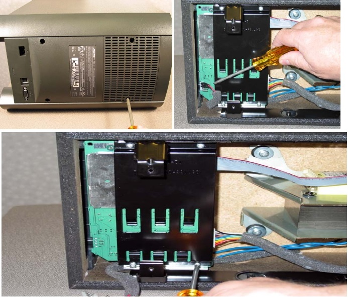
1. Rear Enclosure Removal
1.1 Place the bass module on its side. Using a phillips-head screwdriver, remove the four screws that secure the rear enclosure to the bass module cabinet.
1.2 Lift the rear enclosure partially off of the bass module.
1.3 Unplug the transformer primary cable at J5 on the input/output PCB located on the back of the rear enclosure.
1.4 Unplug the two ribbon cables at J6 and J7 that run from the input/output PCB to the main PCB. Lift the rear enclosure away from the bass module cabinet.
2. Main PCB Removal
2.1 Perform procedure 1.
2.2 Unplug the woofer harness from the main PCB at J350. This harness plugs into the connector through the holes in the bottom of the main PCB.
2.3 Using a phillips-head screwdriver, remove the four screws that secure the heatsink bracket to the heatsink. Lift off the heatsink bracket.
2.4 Carefully lift the main PCB away from the heatsink. Unplug the
power transformer secondary harness from the main PCB at J5. Rotate the main
PCB clear of the cabinet until it is at about 90 degrees from the heatsink. At
this point, you should be able to lift the PCB clear of the rear enclosure mounting
brackets.
3. Power Transformer Removal
3.1 Perform procedure 2 to remove the amplifier/DSP PCB.
3.2 Using a soldering iron, apply heat to the head of one of the screws that secure the transformer to the bass module cabinet. Apply heat for about 20 seconds. Immediately after removing heat from the screw head, use a phillips-head screwdriver to remove the screw. Repeat this for the other three screws.
Heating the screw head releases the threadlock adhesive that is used on these screws in manufacturing.
3.3 Lift the power transformer out of the cabinet.
4. Input/Output Board Removal
4.1 Perform procedure 1 to remove the rear enclosure.
4.2 Using a phillips-head screwdriver, remove the two screws that secure the input/ output board bracket to the rear enclosure. Lift off the bracket. Slide the input/output board out of the rear enclosure.

STANDARD SATELLITE ARRAY DISASSEMBLY
PROCEDURES
Notes:
# The standard satellite arrays are nonrepairable. These are the arrays that have the cloth grilles, and are physically larger than the GemstoneTM array.
# The only parts that can be replaced on the standard arrays are the grille and the nameplate. Refer to the photos at right for the following procedures.
1. Grille Removal
1.1 Wrap some masking tape around the shaft of a flat-tip screwdriver approximately 1/2" back from the end. This is needed to protect the plastic enclosure of the array.
1.2 Place the satellite array on its back on a bench. Use your thumb to press down on the array grille at the center of the curve near the side. At the same time, use the screwdriver to pry the end of the grille off of the array enclosure. Repeat this at the other end of the grille.
Re-Assembly Note: Align the grille so that the Bose logo is facing the same direction as the arrows on the front of the array enclosure. Press the grille in place. It should latch to the enclosure at each end.
GEMSTONE SATELLITE ARRAY DISASSEMBLY PROCEDURES
1. Grille Removal
1.1 Using a scribe or small flat-tip screwdriver, grasp the edge of the grille. Gently pull the grille away from the enclosure.
2. Driver Removal
2.1 Perform procedure 1.
2.2 Using a Phillips-head screwdriver, remove the four screws that secure the driver to the enclosure. Lift the driver out of the enclosure and cut the wires as close to the driver as possible.
